Fuses and relay Hyundai Accent 2006-2011
For the Hyundai Accent (Hyundai Brio, Hyundai Avega, Hyundai Verna, Dodge Attitude, ) 2006, 2007, 2008, 2009, 2010, 2011 model year.
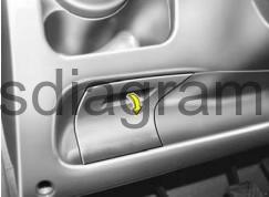
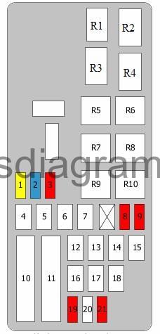
Fuse box in passenger compartment.
The fuse box will be found low on the dashboard on the driver's side.
fuse box diagram.

legend.
| Fuse | Amps | Circuits protected |
|---|---|---|
| 1 | 10A | Starter relay Relay box in passenger compartment, relay R1 (2010-) |
| 2 | 10A | Instrument cluster |
| 3 | 10A | Hazard warning switch |
| 4 | 10A | Hazard warning light relay (-2009) Relay box in passenger compartment, relay R3 (2010-) |
| 5 | 10A | Rear right combination light Number plate light(s) Right headlight Connector |
| 6 | 10A | Rear left combination light Number plate light(s) Left headlight Daylight running system control unit (-2009) |
| 7 | 10A | Engine control unit |
| 8 | 25A | Driver's power window switch Switch, rear left power window(s) |
| 9 | 15A | Audio |
| 10 | 10A | Luggage compartment light Interior light Vanity light Digital clock Overhead console Air-conditioning control unit Instrument cluster Warning buzzer Door open Body control unit (BCM) |
| 11 | Spare fuse | |
| 12 | 10A | Airbag switch (-2009) Not used (2010-) |
| 13 | 10A | Overdrive main switch TCM (2010-) |
| 14 | 15A | SRS control unit |
| 15 | 30A | Body control unit (BCM) Rear demister |
| 16 | 10A | Headlight levelling switch Demister (2010-) |
| 17 | 10A | Rear combination light(s) Rear fog light switch Body control unit (BCM) |
| 18 | 10A | Folding mirror (-2009) |
| 19 | 25A | Driver's power window switch Power window switch, front passenger Switch, rear right power window(s) |
| 20 | 10A | Body control unit (BCM) Demister (2010-) |
| 21 | 10A | Engine control unit |
| 22 | 10A | Daylight running system control unit |
| 23 | 10A | Front fog light switch Front left fog light Front right fog light Body control unit (BCM) |
| 24 | 25A | Amplifier |
| 25 | 20A | Driver's seat heater switch Heated front seat(s) switch |
| 26 | 10A | Exterior mirror (-2009) not used (2010-) |
| 27 | 25A | Cigarette lighter Power outlet |
| 28 | Spare fuse | |
| 29 | 10A | Rear light switch Or Rear light switch Transaxle range switch |
| 30 | 10A | Electronic stability program (ESP) switch Steering angle sensor ABS control unit ESP control unit Multi-purpose check connector |
| 31 | 15A | Ignition coils 1 – 4 Condenser |
| 32 | 20A | Door lock actuator, front left Door lock actuator, front right Door lock actuator, rear left Door lock actuator, rear right Body control unit (BCM) Driver's power window switch Rear-door lock actuator |
| 33 | 15A | Data link connector Brake light switch Power window relay Multi-purpose check connector |
| 34 | 20A | Sunroof motor |
| 35 | 10A | Right headlight Instrument cluster Daylight running system control unit |
| 36 | 10A | Humidity sender In-car temperature sensor Air-conditioning control unit Body control unit (BCM) Blower relay Sunroof motor Or Humidity sender In-car temperature sensor Air-conditioning control unit Body control unit (BCM) Blower relay Sunroof motor PTC heater, relay 2 PTC heater, relay 3 |
| 37 | 25A | Front wiper motor Multifunction switch |
| 38 | 10A | Left headlight |
| 39 | 15A | Multifunction switch Rear wiper motor |
| R1 | Front fog light relay | |
| R2 | Power window relay | |
| R3 | Rear heater relay | |
| R4 | Rear fog light relay | |
| R5 | Door unlock relay | |
| R6 | Door unlock relay |
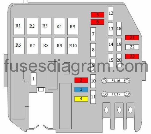
Fuse box in engine compartment.
fuse box diagram (-2009).
| Fuse | Amps | Circuits protected |
|---|---|---|
| 1 | 20A | Engine control unit Powertrain control unit (PCM) |
| 2 | 15A | Injectors (cylinders 1 – 4) Gearbox oil cooling valve Immobiliser control unit Canister purge solenoid Idle speed actuator |
| 3 | 10A | Air-conditioning relay Radiator fan relay Condenser fan relay 1 Condenser fan relay 2 Camshaft position sensor Oxygen sensors Mass airflow meter |
| 4 | 40A | ABS control unit ESP control unit Multi-purpose check connector |
| 5 | 40A | ABS control unit ESP control unit Multi-purpose check connector |
| 6 | 30A | Fuse and relay box in passenger compartment |
| 7 | 40A | Blower motor Blower relay |
| 8 | 10A | Air-conditioning relay |
| 9 | 10A | Air-conditioning control unit |
| 10 | 80A | EPS control unit |
| 11 | 125 | Generator |
| 12 | 50A | Fuse and relay box in passenger compartment |
| 13 | 30A | Main relay Fuel pump relay |
| 14 | 30A | Condenser fan relay 1 Radiator fan relay |
| 15 | 30A | Condenser fan relay 1 |
| 16 | 30A | Ignition switch |
| 17 | 40A | Ignition switch Starter relay |
| 18 | 30A | Fuse and relay box in passenger compartment |
| 19 | 10A | Engine control unit Powertrain control unit (PCM) |
| 20 | Not used | |
| 21 | 10A | Horn relay Security alarm system relay |
| R1 | Horn relay | |
| R2 | Fuel filter heater relay | |
| R3 | Main relay | |
| R4 | Blower relay | |
| R5 | Fuel pump relay | |
| R6 | Starter relay | |
| R7 | Radiator fan relay | |
| R8 | Condenser fan relay 1 | |
| R9 | Condenser fan relay 2 | |
| R10 | Air-conditioning relay |
fuse box diagram (2010 -).
| Fuse | Amps | Circuits protected |
|---|---|---|
| 1 | Spare fuse | |
| 2 | 10A | Air-conditioning relay Radiator fan relay Condenser fan relay 1 Condenser fan relay 2 Camshaft position sensor Oxygen sensors Brake light switch |
| 3 | 15A | Injectors (cylinders 1 – 4) Gearbox oil cooling valve Immobiliser control unit Canister purge solenoid Idle speed actuator Fuel pump relay |
| 4 | 20A | Engine control unit Powertrain control unit (PCM) |
| 5 | 10A | Air-conditioning control unit |
| 6 | 10A | Air-conditioning relay |
| 7 | Spare fuse | |
| 8 | 40A | Blower relay Blower motor |
| 9 | 30A | Fuse and relay box in passenger compartment |
| 10 | 40A | ABS control unit ESP control unit Multi-purpose check connector |
| 11 | 40A | ABS control unit ESP control unit Multi-purpose check connector |
| 12 | 30A | Condenser fan relay 1 |
| 13 | 30A | Condenser fan relay 1 Radiator fan relay |
| 14 | 30A | Main relay Fuel pump relay |
| 15 | 50A | Fuse and relay box in passenger compartment |
| FL16 | 125A | Alternator |
| FL17 | 80A | EPS control unit |
| 18 | 30A | Fuse and relay box in passenger compartment |
| 19 | 40A | Starter relay Ignition switch |
| 20 | 30A | Ignition switch |
| 21 | 10A | Horn relay Relay box in passenger compartment, relay R2 |
| 22 | Not used | |
| 23 | 10A | Engine control unit Powertrain control unit (PCM) |
| R1 | Fuel filter heater relay | |
| R2 | Blower relay | |
| R3 | Starter relay | |
| R4 | Condenser fan relay 1 | |
| R5 | Air-conditioning relay | |
| R6 | Horn relay | |
| R7 | Main relay | |
| R8 | Fuel pump relay | |
| R9 | Radiator fan relay | |
| R10 | Condenser fan relay 2 |
Source: https://fusesdiagram.com/hyundai/fuses-and-relay-hyundai-accent-2006-2011.html
Posted by: jordanyouncesomedaed.blogspot.com
